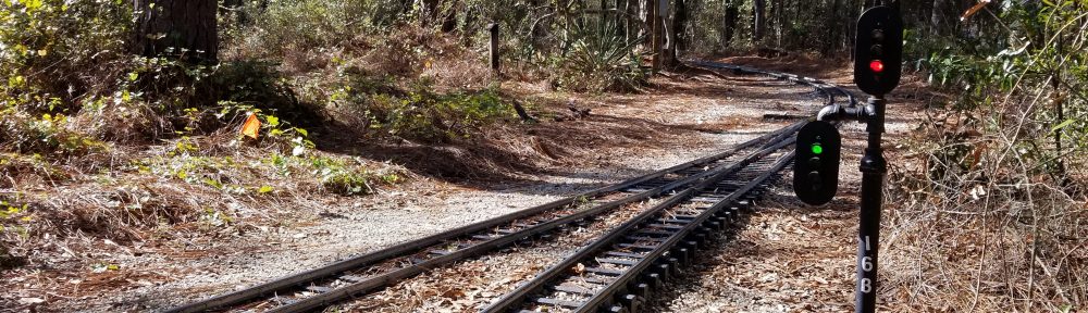

In an attempt to keep costs down but still have “Automatic Signals” some railroads have turned to systems that do not use “Track Circuit train detection” but rather “Trip Tracks” or “Axle Counting”. I will discuss why these systems should be avoided if possible.
In an attempt to overcome the drawbacks of relay-based automatic signal systems (see: Problems With Traditional Approaches To Automatic Signals) or where ‘Track Circuit Detection’ is impossible (i.e.: welded steel rail with welded steel ties), some railroads implement methods of detecting trains passing a given point such as ‘Trip Tracks’ (short sections of track that detect axles) or ‘Axle Counting’ (mechanical or optical means of counting axles).
Virtually all these approaches that I have seen involve a timer or manual reset to handle cases where there was a miss-count, double-count, etc. This causes them to be susceptible to False Clear or False Occupied indications.
To avoid this, a railroad must have detailed rules and procedures to reset a block when a miss-count occurs.
There are prototype mainline railroads that incorporate axle counting. The ‘reset’ usually involves a train traversing the block at ‘Dead Slow’ while in direct communication with the dispatcher. After the train exits the block, the dispatcher manually resets the status of the block to ‘Clear’.
In the ride-on railroad hobby this would be cumbersome at a large meet and we know that you can not always rely on visiting engineers to follow the rules!
To address railroads where track-circuit detection is impractical (welded ties, etc.) I am developing a “wheel Counting” detector. It will count wheels as well as detect train reversal (i.e.: train partially enters the block and then backs out), be immune to people/animals stepping on the rail, branches falling on the rail, etc. Contact me for details.
As our track has welded ties and is continuous track, how are the actual sensors installed. Also, with the signal from the sensor, is it active high or active low i.e. no train the signal is high and when a train goes over the sensor it goes low.
Your advice to this would be greatly appreciated.
I have suspended work on the sensor mentioned in the article due to lack of customer interest. In either case it was designed to work in conjunction with logic in my controller firmware.
Active high/low is inadequate. The sensor is designed to count wheels going in or out of a section of track. To do this it must also know which direction the wheel was going in case, for example, two cars of a four car train go in, stop, and then reverse.
The sensor was designed to output a signal similar to the signal A-B quadrature rotary encoders put out: two square wave signals that are out of phase.
If there is enough interest in it, I can re-activate that project.
Check out the web real-time track display my software supports for one of my customers (updated every 5 seconds):
http://ridgelivesteamers.tplinkdns.com:7751/
Most activity will be on weekends during daylight hours here in the eastern USA but likely to see activity any day.